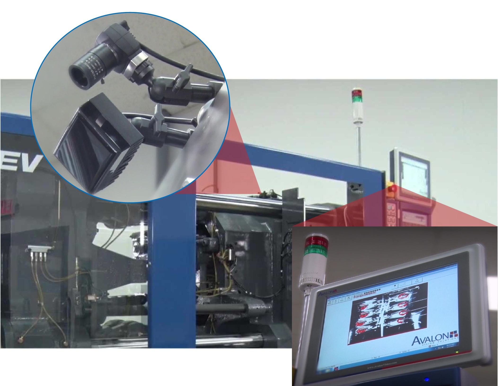

Connecting an Avalon MoldWatcher™ system to a horizontal injection molding machine can be straightforward—especially when the machine has a fully operational EUROMAP 12 or EUROMAP 67 robot interface.
With the Avalon SPI QuickConnect, MoldWatcher can receive the machine signals needed to time its inspections and, when an inspection fails, inhibit selected machine actions to help prevent costly mold damage.
Connecting MoldWatcher With the Avalon SPI QuickConnect
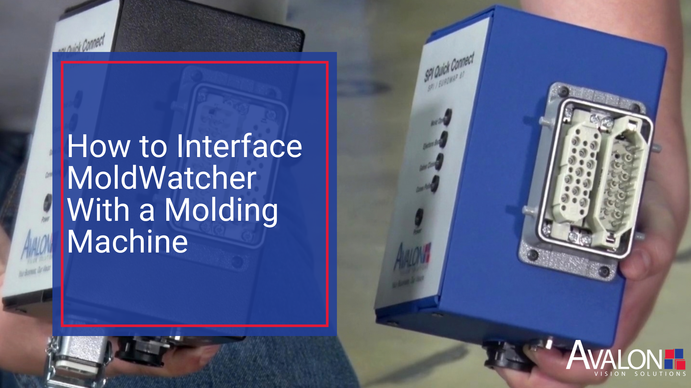
When the molding machine and robot use a compatible EUROMAP 12 or EUROMAP 67 interface, the basic connection process can be as simple as:
- Stop the injection molding machine and home the robot.
- Disconnect the robot from the machine’s EUROMAP 12 or EUROMAP 67 interface.
- Connect the Avalon SPI QuickConnect between the robot and the molding machine.
The QuickConnect allows the MoldWatcher system to access the necessary machine signals while maintaining normal communication between the robot and the molding machine.
All connections should be completed by qualified personnel in accordance with the machine manufacturer’s instructions and the facility’s established electrical and safety procedures.
What Does the MoldWatcher Interface Do?
MoldWatcher uses signals from the injection molding machine to determine when an inspection should occur during the molding cycle.
Depending on the application and the machine’s on/off signal states, the system can inspect the mold for conditions such as:
- Presence or absence of molded parts
- Presence or absence of inserts
- Correct positioning of cores
- Correct positioning of lifters or other moving components
If an inspection fails, MoldWatcher can inhibit specific machine actions, such as mold closure or ejector extension. Stopping these actions before the next step in the cycle can help protect the mold from expensive damage and prevent unnecessary production downtime.
Benefits of the SPI QuickConnect
Using a compatible robot interface eliminates much of the signal identification and individual wiring that might otherwise be required between the press and the vision system. This can provide several practical benefits:
- Faster installation and system setup
- Simplified signal wiring
- Reduced interruption to production
- Continued communication between the robot and molding machine
- Easier relocation of the vision system to another compatible machine
The interface does not replace the robot connection. Instead, it connects between the robot and the molding machine so MoldWatcher can receive and transmit the signals required for the inspection process.
What If the Machine Does Not Have EUROMAP 12 or EUROMAP 67?
Not every injection molding machine has an available EUROMAP 12 or EUROMAP 67 robot interface. A different connection method may also be required when an Avalon vision system is used with another type of machine or manufacturing process.
In these applications, the necessary signals can be wired through an Avalon ENet I/O module.
The compact ENet I/O module provides:
- Eight digital inputs
- Eight digital outputs
- Local signal wiring inside the machine’s control cabinet
- Ethernet communication with the Avalon vision controller
Because the module can be installed inside the machine’s control cabinet, signals can be wired locally and then carried to the MoldWatcher controller through a standard Ethernet cable.
Confirm That the Robot Interface Is Fully Operational
A visible robot connector does not always mean the machine has a fully operational EUROMAP robot interface.
Some newer horizontal injection molding machines are sold with the robot integrated into the press as a complete package. These machines may appear to have a standard robot connector, but the connection might not function as an independent EUROMAP 12 or EUROMAP 67 interface because the robot communicates with the press through a different integrated system.
Before selecting the interface, confirm the machine’s capabilities by:
- Reviewing the press documentation
- Consulting the injection molding machine manufacturer
- Verifying that the available EUROMAP connector operates as a complete robot interface
This confirmation should occur during the project-definition stage rather than waiting until installation.
Why Interface Selection Matters
Selecting the correct interface early can reduce installation time, simplify system setup and limit production interruptions. It can also make it easier to move the MoldWatcher system to a different molding machine in the future.
The appropriate interface will depend on:
- The molding machine manufacturer and model
- The robot configuration
- Whether a functional EUROMAP 12 or EUROMAP 67 interface is available
- The signals required for the inspection sequence
- Whether the press and robot are independently connected or integrated as a single system
Evaluating these details before installation helps Avalon determine whether the application is best served by the SPI QuickConnect or an ENet I/O module.
Frequently Asked Questions
How does MoldWatcher connect to an injection molding machine?
If the machine has a fully operational EUROMAP 12 or EUROMAP 67 robot interface, an Avalon SPI QuickConnect can be installed between the robot and the molding machine. If a compatible interface is unavailable, the required signals can be wired through an Avalon ENet I/O module.
Does the SPI QuickConnect interrupt communication with the robot?
No. The SPI QuickConnect is designed to allow normal communication between the robot and the molding machine to continue while providing the signals required by the MoldWatcher system.
What happens when a MoldWatcher inspection fails?
Depending on the application and system configuration, MoldWatcher can inhibit actions such as mold closure or ejector extension. This helps prevent the machine from continuing the cycle when a part, insert, core or other monitored component is not in the expected condition.
Can MoldWatcher be moved to another molding machine?
Yes, but the connection requirements of the new machine must be evaluated. Selecting the appropriate interface during the original project-definition process can make future relocation faster and easier.
Does every EUROMAP connector work with the SPI QuickConnect?
Not necessarily. Machines with integrated robot-and-press packages may have a connector that resembles a standard robot interface but does not operate independently as one. Always confirm compatibility through the machine documentation or manufacturer.
Discuss Your MoldWatcher Interface Requirements With Avalon
Choosing the correct interface begins with understanding the molding machine, robot configuration and inspection sequence.
Avalon Vision Solutions can review your application and help determine whether the SPI QuickConnect or ENet I/O module is the appropriate connection method for your MoldWatcher system.
Contact Avalon Vision Solutions to discuss your application.
Moving cores make complex molded parts possible. But when Mispositioned Cores occur, the risk is immediate: flash, part damage, broken components, or a mold crash during close.
Mispositioned Cores do not have to be dramatically out of place to cause damage. A moving core that is slightly short of home can still cause interference and poor shutoff contact. It can also lead to metal-to-metal impact when clamp force is applied.
This guide covers the root causes of Mispositioned Cores, the early warning signs teams often miss, and the best prevention step: verify core position before mold close.
What Is a Moving Core?
A moving core is a mold component that shifts into and out of position to form geometry that cannot be produced with a simple open-and-close mold design. Core pulls are commonly used for undercuts, side holes, internal threads, and other features that require movement outside the main mold-opening direction. ZetarMold and Protolabs both describe side actions/core pulls as a solution for features that would otherwise prevent normal part release.
In production, the core must be in the correct position at the correct time:
- Core in / forward: during injection and packing
- Core out / retracted: before part ejection, depending on the mold sequence
- Core home / confirmed: before the next close
When that sequence drifts, damage can happen quickly.
Why Mispositioned Moving Cores Cause Mold Damage
Moving cores create shutoff areas, alignment surfaces, and mechanical interfaces that depend on repeatable positioning. If the core is not fully seated, the mold may still attempt to close or inject against an incomplete shutoff.
That can lead to:
- Shutoff damage
- Core face wear or galling
- Bent or broken pins
- Cracked inserts
- Flash around core-pulled features
- Part sticking or deformation
- Unplanned downtime
Core-pull timing is especially important because the core must move at the correct point in the cycle to avoid part defects or tool damage. Huarong notes that movable cores must enter, remain clamped during filling/packing, and retract according to the correct production sequence.
Root Causes of Moving Core Mispositioning
1. Debris or Buildup in the Core Path
Small contamination can stop a moving core from fully seating. Flash strings, regrind dust, grease buildup, material flakes, or metal chips can collect in the core path or shutoff area.
Quick checks:
- Inspect the core path for packed debris
- Look for flash buildup near the core shutoff
- Check for grease mixed with dust or fines
- Clean the core pocket and verify smooth movement
If flash suddenly appears around a core-pulled feature, incomplete seating should be investigated early.
2. Wear on Sliding or Guiding Surfaces
Moving cores rely on repeatable travel. Wear on gibs, wear plates, guide surfaces, heel blocks, or locking surfaces can change the “true” seated position over time.
As wear increases, the core may still move, but not return with the same precision.
Quick checks:
- Compare witness marks against known-good condition
- Look for uneven shiny rub marks
- Inspect for galling or scoring
- Check whether the core sits flush when manually verified during maintenance
Premature wear is a known issue in core-pull mechanisms because sliding surfaces cycle repeatedly during production. ZetarMold notes that core slides can wear progressively, opening clearances and contributing to flash.
3. Timing or Sequence Drift
A moving core may be mechanically healthy but still mispositioned because the sequence is off. Timing problems often show up after:
- Startup
- Mold changeover
- Cycle-time reduction
- Robot or EOAT adjustment
- Hydraulic/pneumatic setting changes
- Process optimization
If the core moves too early, too late, or too slowly, it may not be where the mold expects it to be.
Quick checks:
- Does the issue appear only at full cycle speed?
- Does slowing the cycle temporarily solve it?
- Did the issue start after a process or automation change?
- Are core-in and core-out confirmations happening at the right point?
Core-pull timing errors can create deformation, cracking, or core damage if the movement happens at the wrong point in the cycle. ZetarMold identifies timing errors as a common core-pull problem.
4. Weak or Inconsistent Actuation
Hydraulic, pneumatic, and mechanical core pulls all depend on reliable force and repeatable motion. If the force is inconsistent, the core may stop short or return unevenly.
Possible causes include:
- Low hydraulic pressure
- Air pressure variation
- Cylinder wear
- Leaks
- Binding
- Weak return springs
- Mechanical interference
Quick checks:
- Watch for slower core movement over time
- Check pressure settings and repeatability
- Inspect cylinders, fittings, and hoses
- Confirm the core reaches full travel every cycle
Inconsistent extraction force can cause deformation, poor part quality, and downtime. Spark Mould lists inconsistent core extraction force and misalignment as common core-pull sequence failures.
5. Misalignment
A moving core that is not aligned with the mold can bind, wear unevenly, or stop short. Misalignment may come from wear, poor maintenance, installation issues, or damaged guiding components.
Quick checks:
- Inspect for uneven wear on one side of the core
- Check guide components and locking surfaces
- Confirm alignment after maintenance or mold repair
- Watch for repeated damage in the same location
Core misalignment can increase wear and cause poor part quality or mold damage. Spark Mould specifically identifies core misalignment as a failure mode that can lead to increased wear and mold damage.
6. Lubrication Problems
Lubrication issues can cause two opposite problems:
- Too little lubrication increases friction and galling
- Too much lubrication attracts debris and buildup
Either condition can prevent smooth, repeatable core movement.
Quick checks:
- Look for dry scoring on sliding surfaces
- Check for heavy grease collecting debris
- Confirm lubrication type and interval
- Verify movement after cleaning and lubrication
7. Sensor or Confirmation Issues
A core-position sensor may confirm movement without confirming full seating. This is especially risky when the core is close enough to trigger a signal but not actually in the correct final position.
Quick checks:
- Confirm the sensor is detecting the correct position
- Check for loose brackets or sensor drift
- Compare sensor confirmation to physical core position
- Verify both core-in and core-out signals where applicable
Core position confirmation is commonly part of core-pull control, especially with hydraulic or pneumatic systems. Huarong describes core-pull process control as a production requirement for reliable operation.
Early Warning Signs
Teams should investigate before damage escalates when they see:
- Flash near core-pulled features
- Intermittent core-position alarms
- New witness marks or rub lines
- Parts sticking around core features
- Cracked or deformed undercut areas
- Cycle time inconsistency
- Core movement that sounds or feels different
- Damage repeating in the same shutoff area
These are often signs that the core is not seating, retracting, or sequencing consistently.
Quick Troubleshooting Flow
Step 1: Confirm the Failure Mode
Determine whether the issue is:
- Core not fully seated
- Core not fully retracted
- Core moving too early or too late
- Sensor confirming incorrectly
- Part sticking and interfering with core movement
Step 2: Check for Physical Blockage
Start with the simple causes first:
- Flash strings
- Material dust
- Grease buildup
- Metal chips
- Part fragments
- Shutoff debris
Step 3: Inspect Wear and Alignment
Check:
- Guide surfaces
- Wear plates
- Core face
- Locking surfaces
- Pins and bushings
- Witness marks
Step 4: Verify Actuation
Review:
- Hydraulic pressure
- Pneumatic pressure
- Cylinder movement
- Spring condition
- Mechanical linkage
- Speed and repeatability
Step 5: Confirm Timing and Detection
Check:
- Core-in signal
- Core-out signal
- Sequence timing
- Machine settings
- Robot/EOAT timing
- Recent process changes
Prevention Before Close
The best prevention point is before mold close, when the next cycle has not yet applied force.
Before close, verify:
- Part is removed
- Moving cores are in the correct home position
- Slides and lifters are returned
- Ejector plate is fully returned
- Mold area is clear
- Sensors or vision confirmation match the actual condition
This is where mold protection can help. Vision-based mold protection is used to verify mold-clear conditions and component positions before the next close, reducing the chance of a close-on-component event. Plastics Technology describes vision mold protection as a way to inspect the mold area before closing.
Download the Mold-Clear Checklist (PDF)
Use this 1-page checklist to verify part release, moving cores at home, slides/lifters returned, and mold area clear before the next close. [Download the checklist]
FAQs
What causes moving cores to become mispositioned?
Common causes include debris, wear, timing drift, misalignment, weak actuation, lubrication issues, and sensor confirmation problems.
Why is a mispositioned moving core dangerous?
A mispositioned core can create interference during close, incomplete shutoff contact during injection, or damage to core faces, inserts, pins, and shutoff surfaces.
What is the best early warning sign?
Flash around a core-pulled feature is one of the most common visible indicators. New witness marks, intermittent alarms, or cycle inconsistency should also be investigated.
How can molders prevent moving core damage?
Standardize before-close verification. Confirm the part is removed, cores are home, slides and lifters are returned, and the mold area is clear before the next close.

Avalon Vision Solutions is pleased to announce the promotion of Ricardo Castro from Service Engineer to Operations Manager, effective July 1, 2026.
Ricardo has been an integral part of Avalon Vision Solutions since joining the company in January 2005. During more than two decades with Avalon, he has played a vital role in installing systems, troubleshooting software, testing software upgrades, providing valuable feedback to improve Avalon’s solutions, and maintaining essential manuals and technical documentation.
Throughout his career, Ricardo has distinguished himself through his extensive knowledge, problem-solving ability, attention to detail, exceptional customer support, sound judgment, and natural leadership. His colleagues are enthusiastic about his promotion and fully supportive of his leadership in this new role.
“Ricardo has been a trusted and invaluable member of Avalon for more than 20 years,” said Ed Kachnic, founder and President of Avalon Vision Solutions. “His technical expertise, commitment to our customers, and willingness to support the team have contributed greatly to our success. He has earned the respect and confidence of everyone around him, and I am proud to support him as he takes on this important leadership role.”
As Operations Manager, Ricardo will oversee Avalon Vision Solutions’ day-to-day operations. His responsibilities will include managing and supporting the team, coordinating customer requests, helping address operational and technical needs, and ensuring Avalon continues to provide the high level of service and support its customers expect.
“I am grateful for the opportunity to take on this new role and continue growing with Avalon Vision Solutions,” said Castro. “Avalon has been an important part of my life for more than 20 years, and I am proud of the work our team has accomplished together. I look forward to supporting our employees, serving our customers, and helping guide Avalon into its next chapter.”
Please join us in congratulating Ricardo on this well-deserved promotion.
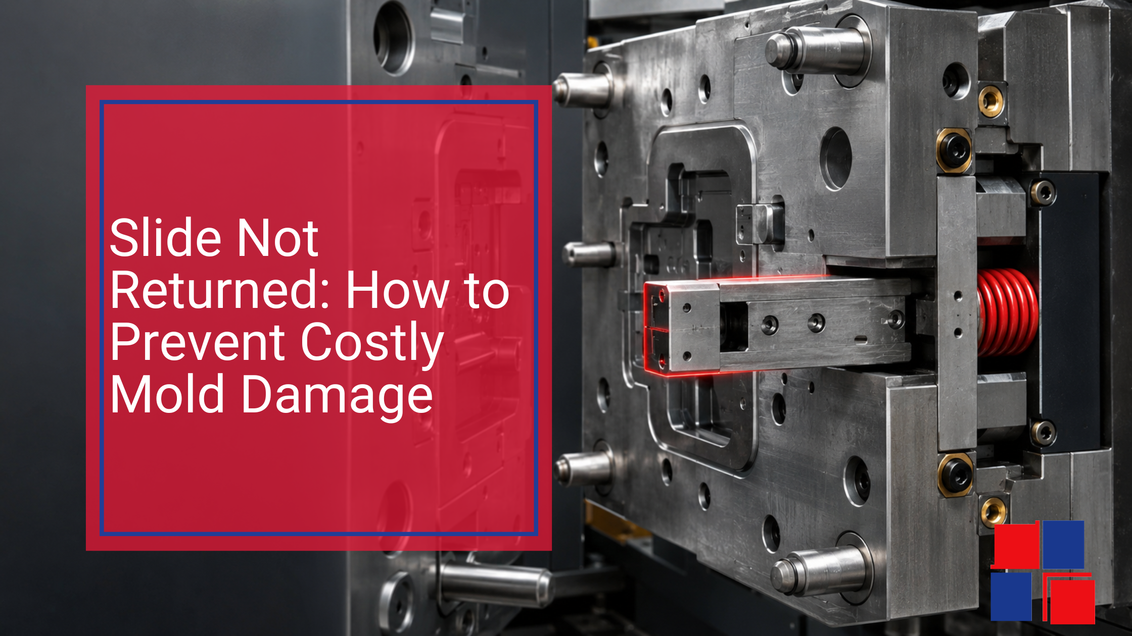
This post gives you:
the most common root causes
early warning signs (before the crash)
a quick-check flow your team can use on the floor
and the highest-leverage prevention step: verify before mold close
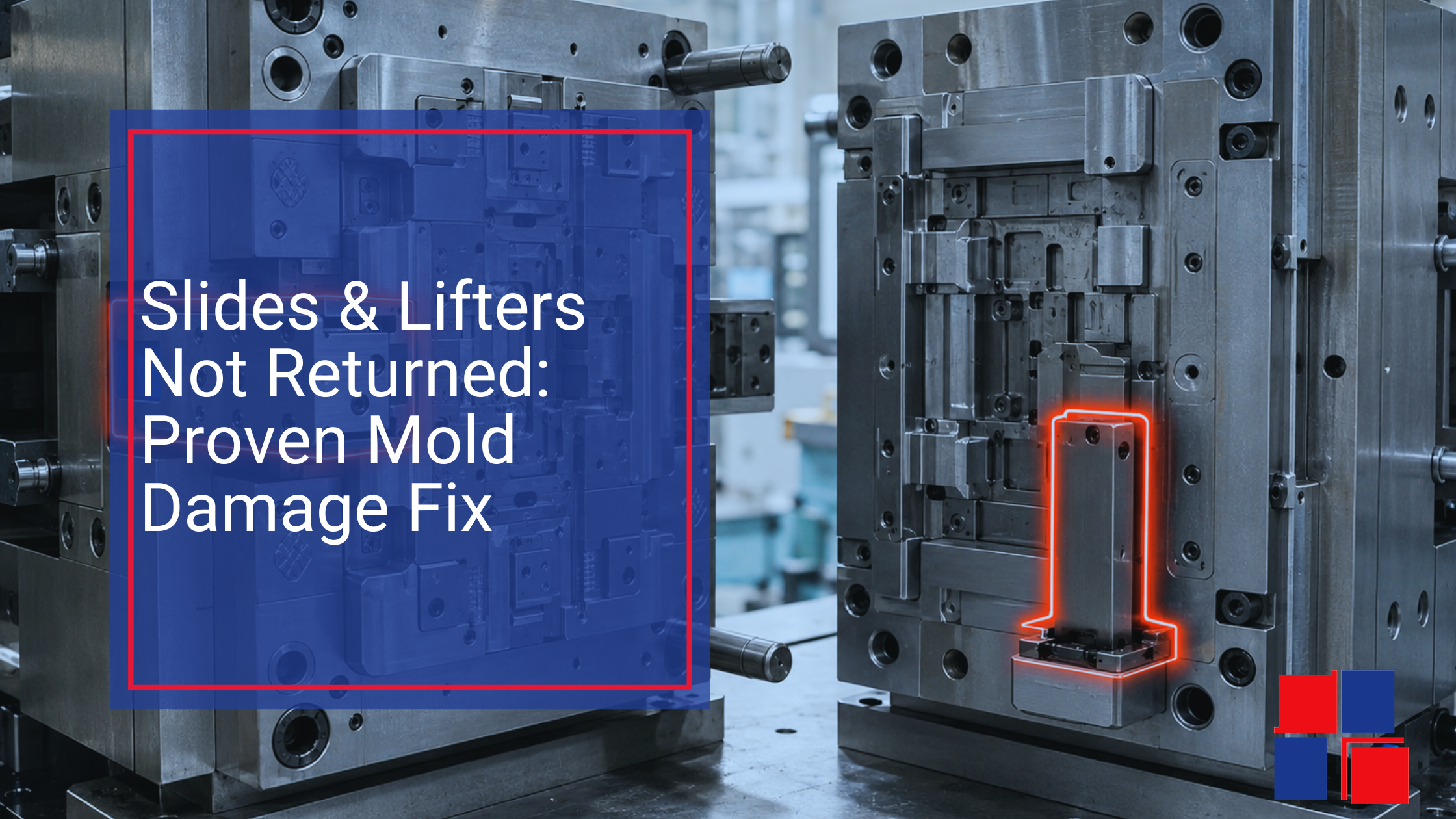
The tricky part? Most “not returned” events are caused by small, repeatable issues that creep in over time - wear, contamination, timing drift, or inconsistent ejection mechanics.
This guide covers:
what “not returned” really means,
the hidden causes that create mold damage,
the warning signs your team can catch early,
and the best prevention move: verify before mold close.
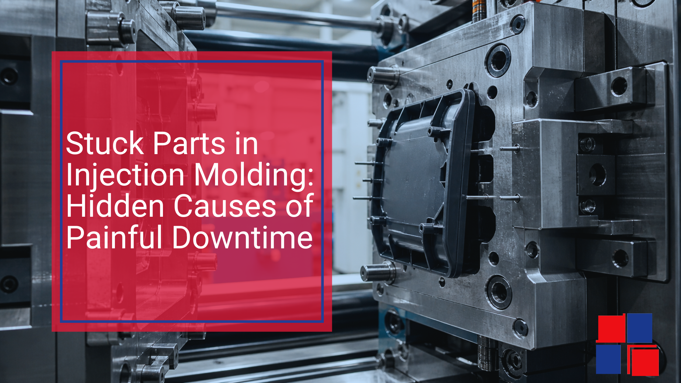
This guide covers:
the most common causes of stuck parts,
the warning signs teams miss,
and a practical prevention checklist—with a focus on reducing risk before mold close.
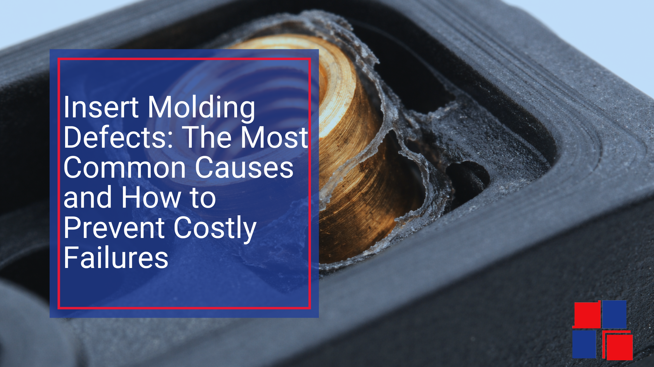
When an insert is missing, doubled, misaligned, or not fully seated, the next mold close can turn into a crash. This article covers the most common insert molding defects, what causes them, how to prevent them, and how vision verification can help you stop crunching molds before damage happens.
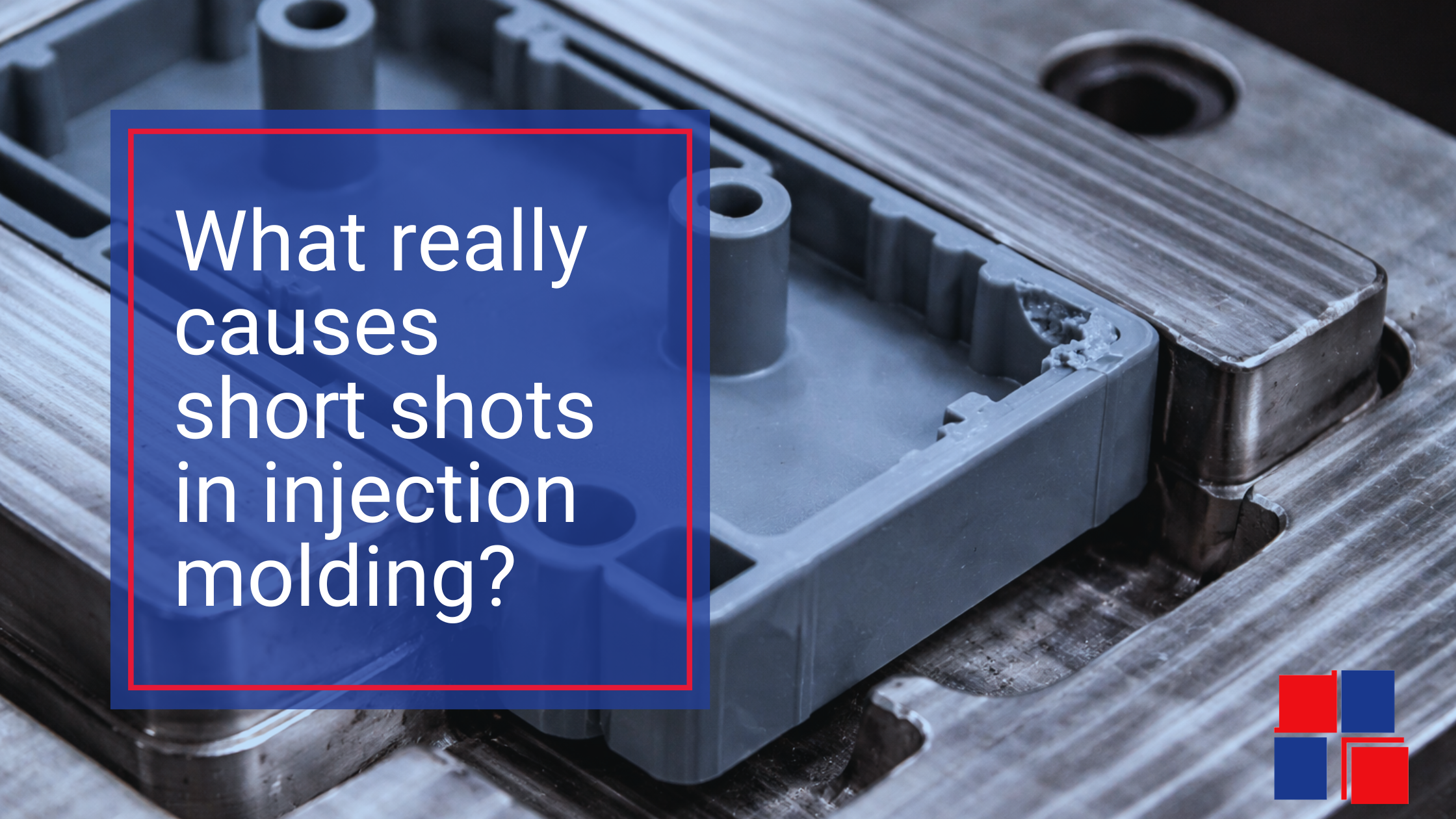
They occur when the mold cavity is not completely filled, leaving portions of the molded part incomplete. The result can be unusable parts, increased scrap rates, and production delays.
For injection molding managers, the challenge is not just fixing short shots after they occur. The real goal is detecting them early and understanding what caused them so the process can be corrected before production losses escalate.